Tuesday, May 1, 2018

ILA 2018 report and why additive manufacturing and biomimicry is a golden combination


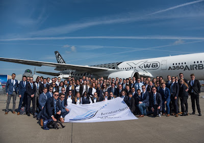
On the 27th of April, I visited the ILA Berlin Airshow with a group of 87 members of the Amsterdam Aviation Association. We were not the only ones; the airshow was visited by about 180.000 visitors this year! This blog will consist of two parts: first a report of the airshow itself and second a part about an interesting combination of technologies I see more and more being introduced: additive manufacturing and biomimicry.

Picture credit to Amsterdam Aviation Association

ILA Berlin 2018

The biggest and heaviest aircraft of all time, the Antonov An-225 paid a surprise visit to ILA Berlin 2018. It was impressive to see this huge aircraft up close. As mentioned in my previous blog post, ILA Berlin is not a show where civil orders take place. On the military side, a ‘battle of the contracts’ took place. Fixed-wing and rotary-wing battles took place to acquire contracts for the replacement of the Panavia Tornado and the CH-53G respectively. As a response to the enquiry of the renewed Eurofighter Typhoons by the German Air Force, Lockheed bade to supply the F-35A to the German Air Force. The Typhoon and Tornado gave an impressive flying display demonstrating combined capabilities. After this display, the Eurofighter Typhoon demonstrated aerobatic craftsmanship with a solo display with AC/DC’s Thunderstruck as ‘background’ music. The roaring Eurojet EJ200 was enough music to my ears, but some AC/DC gave an extra dimension to the show. Next to the ‘battle of the contracts’, Airbus and Dassault announced a cooperation to develop a new combat aircraft to eventually replace the Eurofighter Typhoon and Rafale between 2035 and 2040. The new aircraft has been assigned the name of Future Combat Air System – FCAS. As a “system of systems” the FCAS is intended to combine a wide spectrum of resources. The intention is also to enable this interoperable overall system to be linked up as part of an extensive deployment scenario involving flying missions, satellites, NATO systems as well as land-and sea-based combat systems. The video below is an impression of the airshow.


Video credit to ILA Press Service

3D printing the future: what’s next?

Additive Manufacturing, or 3D printing, is a technique that is being developed in many industries. The most well-known technique is polymer printing. Small, affordable printers are being developed rapidly by a wide range of companies. These printers could be used for rapid prototyping or printing new parts to use as a repair. Many companies are developing new printers as we speak so I expect that in a few years, having a 3D printer will be as normal as having a ‘2D printer’. One does not have to be an expert in 3D designing. Currently, large communities like Thingiverse and Youmagine exist offering a wide range of pre-designed 3D objects, from spare parts of skateboards to printable models of aircraft engines. The principle of polymer printing is rather simple: material is being melted and deposited onto an object, layer by layer. This way of printing yields some design limitations, but creative solutions exist dealing with these limitations.


Next to polymer printing, metal printing is being developed extensively last years. With machining, a lot of the original material was going to waste. Especially for expensive metals like titanium alloys this was a problem: some of the parts required 90% of the block to be machined away. Additive manufacturing eliminates this problem by effectively using almost all material. Next to saving material, printing makes it possible to produce very complex parts rather easily. Demonstrators have shown that (working) complex parts like gearboxes could be printed.

Introducing new parts/production methods in aircraft requires an extensive certification process. Starting with non-flight critical components, 3D printed parts slowly started to replace the machined or casted parts. With the development of the LEAP engine, CFM introduced the first printed engine parts: the fuel nozzle.

Foto credits to General Aviation

Metal additive manufacturing processes could be divided into two categories: deposition printing and powder bed printing. Deposition is similar to polymer printing and uses a print head to spray or melt material onto a previous layer. Where (commercial) polymer printing is usually restricted to three axes (x, y, z) (printing from bottom to top), deposition printing could be performed with a robotic arm where more axis could be used. Using deposition printing this way, it could also be used for repairing or dimensional restoration. Most used materials with deposition printing are titanium-and nickel alloys. Powder bed printing consists of building up an object by selectively melting a profile from a powder bed. After the first layer is melted (or sintered), a new layer of powder is applied and a following profile is melted. This process is repeated until the complete part is printed and the non-melted, excess powder is removed. The video below visualizes this. Power bed could be used for titanium-, nickel- and steel specific applications. Some powder bed printing methods are even fit for all cast-able alloys.


You could imagine that powder bed printing facilitates printing more complex parts but is less suitable for repairs on existing parts/surfaces. Powder bed printing is also rather slow compared to some deposition printing methods.

In general, (metal) additive manufacturing has some disadvantages compared to conventional printing methods:
  • Because the metal is sintered or melted in layers, heat treatments are required to improve the rupture stress of the material;
  • Post machining is required for correct dimensioning: Hot Isostatic Pressing (HIP) is used to reduce the porosity and increase the density of the printed material;
  • To guarantee the quality of the design, each batch of printed parts requires extra quality control and non-destructive testing;
  • Because of high machine and material costs (metal should be produced to powder, which is expensive), it is not attractive enough to replace every conventional machined part by printed parts yet.
Even with considering all the disadvantages, they do not outweigh all the advantages:
  • Additive manufacturing makes it possible to print very complex structures which machining could not. This makes it possible to fabricate lighter structures with the same strength and function which saves fuel costs considering flying parts;
  •  With the reduction of waste material, additive manufacturing saves a lot of costs which makes investing in an expensive machine a lot more interesting;
  • With casted materials, a prefabricated mould is used. When this mould is designed, it is hard to change the design very easily and without more costs. Changing a detail into a printed design much easier and less expensive.

Biomimicry: why imitating birds is suddenly a good idea

The first aviation pioneers thought that imitating a bird got them in the air. They did not realize that a human does not have the same power to weight ratio as a bird and that using a movable wing, like birds, does not work. Some of these pioneers had to pay with their life. The first working aircraft consisted of (massive) wooden bars and unmovable wings which got the first men flying, I think we all know where that got us to. Now, more than 100 years since the Wright Brothers got in the air, we can learn from birds all over again.

Biomimicry is defined as “the design and production of materials, structures, and systems that are modelled on biological entities and processes.” The word is derived from the Greek words ‘βιος’ (Bios) and μίμησις (mimesis) which mean nature and imitation respectively. Biomimicry is applied in a wide range of industries: from product design to architecture. Some examples are the Cellular Chair by Mathias Bengtsson or the Bionic Handling Assistant by Festo. The Bionic Handling Assistant is displayed below. 

Image credit to Festo

In aviation, biomimicry is applied from the start, but was not always successful. Some ‘design features’ from birds have been applied successfully like wing design of soaring birds to gliders. One or the reasons that birds have a larger power to weight ratio compared to humans is the bone structure. The bones of birds are filled with voids and the construction could handle a higher load relatively. This results in requiring less mass and therefore lighter, which raises the power to weight ratio. Compared to aviation, ‘mother nature’ had ‘some extra time’ to optimize the design of birds.

Bird bone structure

In Dutch, we have a saying “Beter goed gejat dan slecht bedacht” (better stolen properly than invented badly). With additive manufacturing being developed more and more and the fact that more complex structures could be printed, it is possible to integrate the bone structure of birds into aircraft parts. This combination of a rather old and new technique makes it possible to construct lighter structures which are able to handle equal or higher loads. At ILA 2018, Liebherr-Aerospace displayed a bell crank bracket being printed. One could see the difference in design with the milled version and the printed version: the structure of a bird’s bone is clearly visible.

\
Picture credits to Liebherr-Aerospace

These designs are being introduced slowly, starting with small parts. Airbus is looking forward and developed a more radical design: instead of using stiffeners, spars and ribs the whole internal structure of the fuselage could be replaced by a ‘bionic 3D printed’ structure. Airbus has started application of parts of this design by introducing a bionic 3D printed passenger compartment/galley separator. The printed structure has 45% the weight of current designs, which could save up 465000 tonnes of CO2 if this part is applied to all A320s. Imagine that a weight reduction a full bionic 3D printed skeleton could result in!

Picture credits to Airbus S.A.S.

To conclude this blog, I think that the combination of additive manufacturing and biomimicry could result into significant fuel savings in the future which contributes to the emission goals set for 2050. With the development of additive manufacturing, it will be feasible to print more and more parts making the investment of a machine more doable for SMEs. With the design having less sharp corners, stresses will be divided more uniform trough the complete structure. This could result in better fatigue performance, extending the lifetime of parts and lowering costs for operators.

This blog was a short review of the ILA Berlin air show I visited on the 27th of April. The biggest surprise was the An-225 and the battle of contracts was very interesting to see. I hope I have given you some insight in additive manufacturing, biomimicry and the possibilities of these techniques. Next blog I will shine a light on one of the most discussed subjects in propulsion today: electric/hybrid propulsion.
Friday, April 20, 2018

ILA Berlin, what to expect?


As a Dutchie, 27 April is a national holiday when we celebrate the birthday of our King, Willem-Alexander. A day of celebration throughout the complete country, but this year I will not be present. I will celebrate Willem-Alexander his birthday by spotting 200+ aircraft at the ILA Berlin Air Show. In this blog I will give a prospect about what I am going to witness at the airshow, in a following blog I will give a report about the visit.
The ILA (Internationale Luft- und Raumfahrtausstellung) Berlin is a bi-annual airshow held at Berlin-Schönefeld airport. ILA Berlin is one of the largest airshows happening today and the location, the Berlin ExpoCenter Airport (at Schönefeld), houses five large halls which is the centre of networking for over 1000 exhibitors. Along these exhibitors are OEMs, suppliers and MRO-service companies in the field of civil and military aviation. The airshow features a static and flying exhibition displaying over 130 unique types featuring UAVs, (military) training aircraft, large airliners, historic aircraft, bizzjets and helicopters.  Next to aviation, aerospace technology will also be on display but will not be discussed in this article.

New aircraft on display at ILA
Airshows are perfect occasions for the aircraft manufacturers to display and demo new types. One of the aircraft I am most excited about is the Sikorsky CH-53K King Stallion, the largest and heaviest helicopter under development for the US Military. It will be competing against the CH-47 Chinook for acquisition by the German Air Force of a replacement for the CH-53. The CH-53K features an aircraft which is powered by three 7500 shp GE38-1B turboshafts and could lift 12 tonnes externally. The CH-53K is promised to give a flight demo and I am exciting to see this humongous helicopter manoeuvre.
The F-35A will make an appearance at ILA 2018 as well. One year ago, at the Paris Air show, the F-35A gave its first areal capability demo. The F-35 is not been scheduled to flight yet, but I keep my hopes up to hear that F-135 engine roaring next week.
The Airbus A340 BLADE (Breakthrough Laminar Aircraft Demonstrator in Europe) will make its debut at the airshow. The A340 BLADE is a demonstrator with two outer transsonic laminar outer-wings, which could drastically decrease the wing friction which results in less fuel and thus fewer emissions, making aviation greener.
This year’s edition features an even bigger spectrum of UAV’s compared to past editions. UAVs as big as the European Male RPAS with a spanwidth of 25m and a MTOW of two tonnes or as small as the Black Hornet Minidrone which fits in your back pocket will be on display. The Zepyhr, Airbus’ solar powered aircraft which soars at 70000 ft and could provide an alternative to satellites.

What’s more?
Next to the newcomers, more civil and military aircraft will be displayed. The flying program offers quite a display from the German Air Force and a demo by the Spanish national display team: Patrulla Águila. The flight schedule features also slots for a ‘UAS exhibitor’ and the ‘ILA highlights’ but as of writing of this blog, no details were provided yet for these slots. At the static display, next to all the ‘state of the art’ aircraft, historic aircraft are displayed. One of my personal favourites, the Douglas DC-3, will be on static as well. For the military-aviation enthusiasts, the show provides enough: aircraft like the C-130J Hercules, NH-90, Eurofighter Typhoon, CV-22A Osprey, E-3A Sentry AWACS, Airbus A400M and many more are confirmed to be on display. For people who come to see big jets, the show provides as well: the Boeing 747-8 and the Airbus A380 shall provide a lot of shadow in the static display area. Overall, it promises to be a show worth visiting!

ILA: the numbers
Analyzing the aircraft list provides some interesting insights. To start with a 3.6 to 1 ratio of military market focused aircraft to civil market focused aircraft. The obvious reason is the wide range of mission types versus ‘conventional’ flying. From small drones to huge troop and cargo transporters, for almost every mission type, several types are offered at ILA.
Comparing all the aircraft categories, military combat- and training aircraft and helicopters/rotorcraft jump out. Within the helicopter/rotorcraft category, the focus is laid on the military market.For civil passenger aircraft, the huge orders usually take place at the Farnborough or the Paris airshow. Comparing the Paris airshow of last year, Boeing displayed the 787-10 and the 737-MAX 9 while Airbus displayed the A380 ‘plus’, the A350-1000 and the A321 neo. This year, Airbus will bring the A380 and A350-900 and Boeing will bring the 747-8 for the civil market.
Next article I will lay more focus on the upcoming technologies I have witnessed myself on the airshow next week. If you are visiting ILA, I hope I provided some more insight on the aircraft on display.


Thursday, April 5, 2018

Suck, Squeeze, Bang, Blow - Aircraft engines, how do they work?


I started blogging with the aim to write technical articles in the field of Aviation. Next to opinion articles focused on readers with a certain background, my goal is to write educational articles. These articles will be focused on Aviation professionals, but with limited knowledge in other fields. I want to kick these articles off with one of my favourite subjects within Aviation Engineering: gas turbines, the power behind your flight.

Figure 1: A JT9D high-bypass turbofan on the 'City of Everett', the first produced Boeing 747 prototype

How does an gas turbine work: the essentials

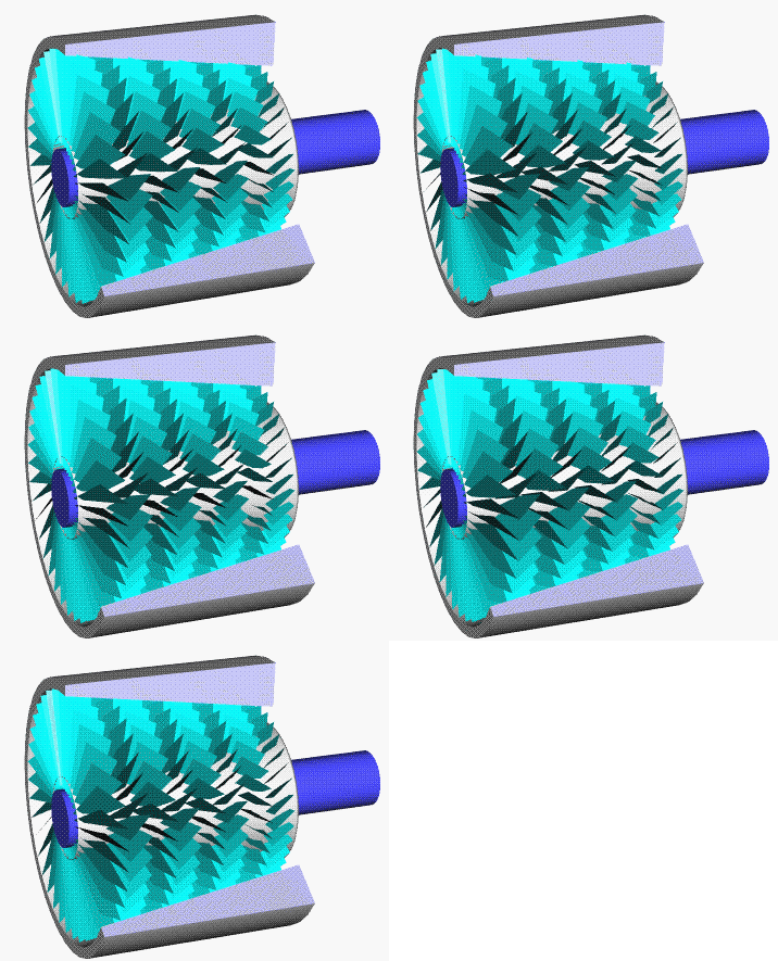
As the title suggests, a simple way to explain the way a gas turbine works is ‘Suck, Squeeze, Bang, Blow’. Air is sucked in, squeezed, ‘blown-up’ and blown away. But how is this possible? Every gas turbine has three basis components: the compressor, the combustor and the turbine. Figure 2 shows the interaction between these three components. Air flows from left to right.

Figure 2: Schematic view of a basic gas turbine

Doing the unnatural: the compressor

The compressor works with the same principle as a bicycle pump: air is rapidly compressed. A bicycle tire is inflated up to pressures of around 6 bars, which is six times the pressure around you. Small gas turbines have similar compression ratios, but there is one difference: the compression of your tire is reached with a lot of (exhausting) pumps, which could take a while. The compression ratio of a gas turbine is reached within the blink of an eye and with a lot more air to compress.  Imagine pumping up your tire in a single stroke, and that is for a small gas turbines. One of the biggest engines currently flying, the GE90 that powers the Boeing 777, has an airflow of about 1400 kg/s. That is sucking in the air of a 100 square meters big hangar every second! The newest developed gas turbines have compression ratios reaching 60! To compare it with water pressure, this is the water pressure at about 600 meters depth. 

To achieve these high pressures, small aerofoils ‘cooperate’ to create a high pressure. Figure 3 shows how an (axial) compressor works: rows of alternating spinning and fixed aerofoils (rotors and stators) push the air through the narrowing compressor. The overall effect is high pressure air. Because air naturally moves from high pressures to low pressures (think about the daily weather forecast), the process within a compressor is very unnatural. For this fact, compressor design is one of the toughest parts within gas turbine design. 

Afbeeldingsresultaat voor axial compressor
Figure 3: An (axial) compressor

The compressor driver: the turbine

The compressor needs a lot of power to achieve the high compression ratio. This power is ‘harvested’ from the turbine. The principle of a turbine is exactly the opposite of the compressor: air moves from high pressure to a lower pressure and energy is used to drive the shaft which powers the compressor. The design of a turbine also consist of moving and static blades, but the blade design itself differ a bit (see Figure 4). The difference is because of the difference in temperature: while the compressor operates in temperature ranges of ambient temperature to 400/500 degrees Celsius, a turbine operates at temperatures around 1200/1300 degrees Celsius (or higher!). To protect the metal blades from melting away, the blades are forged from exotic metals, cooled internally and externally and coated with a ceramic coating.

Figure 4: A compressor blade (left) versus a turbine blade (right).

Where the magic happens: the combustor

A combination of a turbine and compressor could not operate on itself. Because of inefficiencies, extra input of energy is required to keep the compressor and turbine spinning. This is done by the combustion of fuel. This combustion is done with a very high efficiency with the aim to minimize the NOx, SOx and carbon monoxide (CO) emissions. The combustors of older gas turbines are less efficient which results in incomplete combustion (with by-products like soot and carbon monoxide), which clearly could be seen in Figure 6. 


Figure 5: A Boeing 707 in take-off

Future goals are set to repulse emissions by gas turbines and could be seen in Figure 5. The figure means that engines that are been developed by 2020 should emit 50% less carbon dioxide compared to engines developed in 2000. 


Figure 6: ACARE flight path for Europe. Image copyright of Arvind Gangoli Rao and Feijia Yin


Turbofan, Turbojet, Turbowhat?

Within (commercial) aviation, four ‘variants’ of gas turbine exist: turbojets, turbofans, turboprops and turboshafts. These could be divided in two categories: ‘using the power for thrust’ (turbojet & turbofan) and ‘using the power for torque’ (turboprop and turboshaft). Next to delivering power for thrust or lift, gas turbines drive the electric, hydraulic and pneumatic systems of aircraft.

In thrust we trust: the turbofan and turbojet

The turbofan (Figure 8) and turbojet (Figure 7) both rely on the same principle: generating ‘excess’ pressure in the exhaust to generate thrust. You could say that a turbofan is a turbojet with a huge fan mounted on front. The fan, because of the bypass, is more efficient than the turbojet and therefore is applied widely in the civil industry. Modern day turbofans are designed with bigger bypasses to enhance the efficiency.    


Figure 7: a turbojet schematic and the General Electric J85-GE-17A

For military application and in particular for fighter jets, turbofans with high bypass ratios are not useful. For most cases, a turbojet or a turbofan with a low bypass ratio is used. To enhance performance in some scenarios, an afterburner is used. An afterburner is basically a huge combustor mounted within the exhaust, so extra energy is added. With the right use of the exhaust, velocities above the speed of sound could be reached.


Figure 8: A turbofan schematic (left) and the CFM56-2

Small, but powerful: the turboshaft and turboprop

The principle of the turboprop (Figure 9) and turboshaft (Figure 10) is not to generate thrust, but to convert all the power that is generated into torque. The gas turbine is used as a ‘hot gas generator’. The energy from that gas is then extracted mostly by a power turbine: an extra turbine which is not coupled to a compressor but to a gearbox which powers a propeller or (helicopter) rotor. 


Figure 9: Turboprop schematic and the T56-15-LFE

The difference between a turboprop and turboshaft is that mostly one turboprop powers one propeller, but a helicopter rotor could be powered by more than one turboshaft. For instance, the AH-64 ‘Apache’ helicopter has two GE T700 turboshafts, which are both able to power the helicopter by itself. The extra gas turbine is installed to provide (extra) power for certain manoeuvres and for redundancy.


Figure 10: Turboshaft schematic and the T55-GA-714A

What’s else?

Gas Turbines are used for more purposes than described before. The same principle as turboprops and turboshaft could be used to drive anything other than a propeller or rotor. An Auxiliary Power Unit (APU) is a ‘mini’ gas turbine installed in the tail of most (civil) aircraft. The APU provides power for hydraulic, pneumatic and electric systems if the engines are not started yet. The high-pitched sound that could be heard at airports is coming from the APU. It could also be used if both engines fail in mid-flight to power the essential systems to keep the aircraft in control. A deviation from the turboprop is applied in the maritime field. For instance, Areal Commando Frigates use gas turbines for high speeds. Gas turbines are also used to generate high power current. Special gas turbines are designed for energy generation purposes and are enhanced with intercoolers, heat exchangers and are not limited in size. Most of the times a combined cycle is used: steam that is generated with exhaust gasses powers one or more steam turbines. This enhances the total efficiency of the power plant.

Figure 11: Three other major applications of gas turbines: the APU, maritime propulsion and energy generation

What’s next?

Because of environmental boundaries and the depletion of the oil reserves, within this century the aviation industry has to find other means of propulsion. This could be done by using other fuels, going hybrid or even fully electric. I will come back on this subject next month in a separate article on the short- and long term alternatives for gas turbines.

Figure 12: What's next? Image copyright of NASA

I hope I taught you a thing or two about the way gas turbines work. If any questions arise do not hesitate to comment below! Next two blogs I will focus on the ILA Berlin Air Show which I will visit on April 27th. In two separate articles I will preview and review the air show, the aircraft and technologies displayed at the trade visitors’ event.


Thursday, March 8, 2018

Augmented Reality, a useful application for aircraft maintenance?


With the Microsoft HoloLens and the success of Pokémon Go, Augmented Reality (AR) is being developed more and more, the use of augmented reality for industrial applications is coming closer. Aviation is an industry with long certification processes for new technologies like this, but AR applications are being developed as we speak. The use of a Heads Up Display (HUD) is already widely applied to military aircraft and even is used in the newest civil aircraft. But what are the applications of AR in the area of aircraft Maintenance, Repair and Overhaul (MRO)?

(Image source: Netherlands Aerospace Centre)

Safety and cost savings are the number one and two drivers in Aviation (up to you to decide which comes first). Among others, because of extensive (and mostly expensive) maintenance activities, the level of safety remains sky high and the number of casualties as low as possible. However, due to human factors, enough incidents occur that could have expensive effects. Proper training and experience minimizes the risk of these incidents to occur, and AR could help minimize these risks even further. I found some interesting applications of AR that have been developed already in MRO and will discuss them in the next section.

Firstly, Microsoft has demonstrated the application of getting familiar with for instance a turbofan engine (link). From my own experience I could add to this that seeing something in real does add up to the theory you learn in books. Adding AR to this equation could combine these two and even go further. Secondly, Operose has developed an application for the HoloLens, in cooperation with Magnetic MRO, which displays liveries on aircraft (link). It is not an application that could be useful on a daily basis for every MRO, but it demonstrates the way AR could be used to see the application on 1:1 scale. And lastly, the Netherlands Aerospace Centre (NLR), in collaboration with KLM Royal Dutch Airlines, developed a demonstrator for using AR in maintenance training (link).

The use of AR could be applied even further, to the maintenance activities itself. Kingsee demonstrates in this video (link) the application of AR during maintenance tasks. The way certain things are displayed could be improved, but it shows the basic application of AR within the maintenance activities. I expect that steps will be taken to reach a way of working like this, however it has its pros and cons.

Starting with the pros, the major improvement that comes with using AR is a more efficient maintenance and more fault free system. The tonnes of paperwork that came with the old aircraft will become obsolete and all documentation could be done digital which saves a lot of money. With the development of more and more ‘Ditigal Twins’ and 'Big Data', these buzzwords could even be combined. Imagine a line maintenance manager doing a workaround during a turnaround with all the information he or she should have displayed on the focus spots itself? Countless applications could be imagined.
Digital Twins and AR, a golden combination?

Back to using AR in the maintenance process, it will also come with a lot of cons: when looking at the dirty dozen in human factors (link), some came up by imagining the application of AR. Development of a Lack of Assertiveness is one of the first Dirty Dozen that crossed my mind: When personnel gets familiar with using the HoloLens and, by a technical error, information is displayed wrongly, personnel could mindless follow the wrong instructions. Using physical manuals, this problem could be mitigated for the biggest part. Stress is a second Dirty Dozen that crossed my mind: due to being exposed to more inputs than in ‘normal reality’, the stress level could be enhanced that could lead to hazardous situations. When a mechanic has not slept well and a lot of noise is present in the hangar, the stress level could rise to an unwanted level. The last dirty dozen is not the most obvious, but personnel will experience fatigue problems faster when using an application like the HoloLens. The lens works with projecting the augmented reality around you by using a screen right in front of your eyes. Unconsciously, your eyes will switch from focussing to the screen to focussing on the surface where the object is projected on very fast which results in eye sore and higher fatigue for the personnel using the AR application. The research by NLR also mentioned this issue (link).

Due to all the cons I just mentioned, I cannot imagine a future of Aviation MRO without the application of AR. We, as Aviation professionals, should be aware of the Dirty Dozen and the new challenges in the Human Factor area that are linked with applying AR in MRO. In the meantime, developments like MRO AIR are a major stepping stone to the actual application of AR.


Wednesday, February 21, 2018

Why erosion is funest for helicopter engines


Recently, I have started my graduation internship at the Netherlands Aerospace Centre (NLR). During my internship I am trying to map the severity of erosion on a helicopter engine. In this article I will briefly explain why erosion is funest for gas turbine engines, especially for helicopters.

First let me start off by giving a definition on erosion from found literature: Finnie, Wolak and Kabil defined erosion as “The removal of material from a solid surface by the action of impinging solid or liquid particles” [Source 1]. Sundararajan and Roy defined erosion as “the removal of material from component surfaces due to impact of hard particles travelling at substantial velocities” [Source 2], which is a more applied definition to erosion.  Erosion is a broad term which also is used in the geology. The picture below is known as Árbol de Piedra, an eroded rock formation in Bolivia.


The rock is eroded due to grains of sand that have been carried away by the wind and impacted into this rock formation. One grain of sand does not make a difference, but if this happens often enough, one could see the effect: erosion.

This is also a problem for gas turbines, especially the ones operating in sandy environments. Sand that has been ingested in the engines will pass all the blades and vanes inside the gas turbine and will erode them on long term. Especially helicopter engines suffer even more from this erosive effect due to blown up sand due to the downwash of the rotors, also called a ‘brown-out’. The picture below shows a V-22 Osprey demonstrating a brown-out landing. 


Brown-out landings are mostly notorious for the hazard of the loss of situational awareness of the pilot. An example is the crash of a Sikorsky MH-60K Black Hawk of the US Army in Afghanistan, 2001 [Source 3]. The secondary effect of a brown out is excessive sand ingestion in the engine, with more erosion as a result.

What is the effect of erosion on gas turbine components? The late Professor Widen Tabakoff did extensive research into erosion and the effects on gas turbines. He described in his researches, along with other researchers that for the compressor, erosion resulted in (see also the illustration on the right):

  • ·         Blunted leading edges (1);
  • ·         Sharpened trailing edges (2);
  • ·         Reduced blade chords (3);
  • ·         Increased pressure surface roughness (4).


What is the effect of these four erosion results? Overall, the efficiency of the compressor will degrade. What is the effect of compressor efficiency degradation? Higher fuel flows. To explain this, let me start by explaining how a turboshaft engine works. The illustration below is a basic schematic of a turboshaft, a gas turbine engine type applied on helicopters. The green part is designed to deliver a high energetic gas to the purple part, the free power turbine (3). The Free Power Turbine extracts the energy from the gas and transfers it to a power shaft which is coupled by gearboxes to the rotors of the helicopter. The engine is designed in such a way that the Free Power Turbine always delivers the same amount of work on the Power Shaft.


If it happens, due to erosion, that the compressor efficiency drops, it means that the compressor (1) requires more energy which is ‘harvested’ from the compressor turbine (2). This requires more energy from the compressor turbine and, compared to a more efficient engine, would deliver less energetic gas to the Free Power Turbine. To keep delivering a constant amount of work to the Power Shaft, the Free Power Turbine requires more energetic gas and the engine will adjust this by injecting more fuel. More fuel usage means less range or bringing along more fuel which means more costs. Either way, no positive effect for the operator but no hazardous conditions.

A more hazardous effect is the potential of an engine surge, or compressor stall. A compressor is designed to do a very unnatural thing: moving air from low pressure to high pressure. To achieve this, the compressor is designed very precisely. When the compressor blades are off-design, for instance as result of erosion, disruption of air could occur within the engine and the high pressurized air will flow out of the front of the engine: an engine surge. 

This video [link] is an example of what happens during an engine surge. The GE90 engine was mounted on the first 747 during its test program. You could see (and hear) a violent bang with flames coming out of the front of the engine, which is the high energetic gas mixture from the combustion chamber. An engine surge damages the compressor section and will result in an engine shutdown. For a Boeing 747 with three other fine working engines this does not have to end catastrophically, but for a low-flying helicopter it certainly could.

To summarize: brown-outs cause excessive erosion to helicopter engines. Blunted leading edges, sharpened trailing edges, reduced blade chords and increased pressure surface roughness is the effect of erosion. This results in higher fuel usage due to compressor efficiency detoriation and could lead to the potential of engine surges which could end catastrophically to a low-flying helicopter.


Sources:
[1]       Finnie, I., Wolak, J., & Kabil, Y. (1967). Erosion of Materials by Solid Particles. Journal of Materials, Vol. 2, No. 3, 682-700.
[2]       Sundararajan, G., & Manish, R. (1997). Solid particle erosion behaviour of metallic materials at room and elevated temperatures. Tribology International Vol. 30, No. 5, 339-359.
[4]       Hamed, A., & Tabakoff, W. (2006). Erosion and Deposition in Turbomachinery. Journal of Propulsion and Power, 350-360.

Friday, February 9, 2018

Older Article - Sky is the Limit?

Note: This is an older article, written by me, that was posted on Aviationtelegraph.com. Unfortunately, due to inactivity, the website was removed from the Internet.

Older Article - The detachable cabin, a good idea?

Note: This is an older article, written by me, that was posted on Aviationtelegraph.com. Unfortunately, due to inactivity, the website was removed from the Internet.